
Más que un unboxing
Esta primera miniserie documenta el proceso completo de construcción, configuración y prueba de un sistema híbrido Humsienk alrededor de su inversor de 8 kW y una batería LiFePO₄ de 51.2 V y 100 Ah. La meta no era simplemente conectar los equipos y decir que funcionaban. Quería una instalación de prueba que revelara cómo se comporta el sistema, cómo deben organizarse sus protecciones, cómo transfiere entre la red y la batería, y qué ocurre cuando la configuración no sale según lo planeado.
El sistema en el centro del proyecto
La plataforma combina un inversor híbrido Humsienk de 8 kW con aproximadamente 5.12 kWh de almacenamiento LiFePO₄, comunicación BMS, capacidad de 120/240 V, entrada fotovoltaica, el ATS interno del inversor y monitoreo remoto mediante un dongle de comunicación y SOLARMAN.
- Inversor híbrido Humsienk de 8 kW
- Batería Humsienk LiFePO₄ de 51.2 V / 100 Ah
- Aproximadamente 5.12 kWh de almacenamiento de energía
- Comunicación de gestión de batería mediante CAN/RS485
- Operación a 120/240 V, entrada PV, ATS interno y monitoreo mediante SOLARMAN
Construyendo la caja de distribución y protección
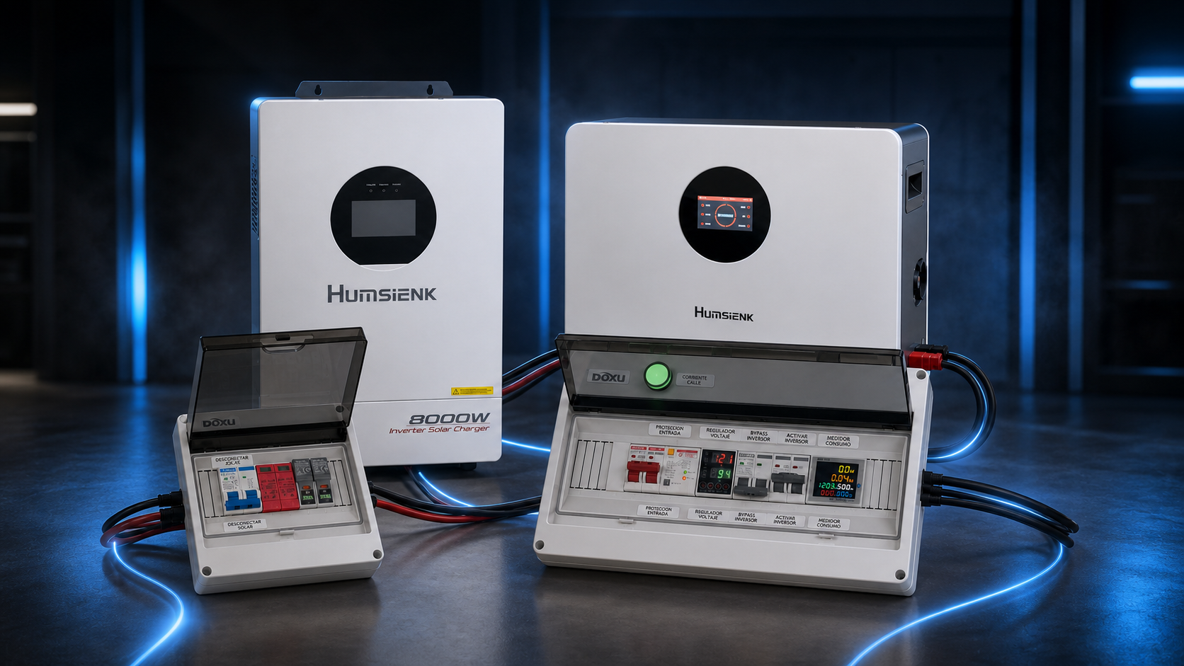
Antes de conectar el inversor, construí una caja de distribución dedicada para organizar la entrada de red, la entrada y salida del inversor, las cargas conectadas, el aislamiento, el bypass y el monitoreo. Los videos muestran los componentes, la preparación de conductores, terminales, ferrules y la lógica del diseño, en lugar de ocultar la infraestructura alrededor del producto.
Un módulo independiente de protección fotovoltaica
La futura entrada solar recibió su propia caja DIN de ocho espacios. El módulo coloca un breaker DC de dos polos, protección contra sobretensiones DC de dos polos, dos fusibles fotovoltaicos de 20 A, entradas y salidas MC4 y cable PV entre los paneles y la entrada PV del inversor. La serie también muestra la distribución interna, los terminales, las herramientas y las modificaciones realizadas a la caja.
Inversor y batería, examinados antes de la instalación
El unboxing del inversor cubre las pinzas CT, el dongle de comunicación, los accesorios de montaje en pared, los terminales de batería, la documentación y el cable de comunicación para múltiples inversores. El episodio de la batería examina la unidad LiFePO₄ de 5.12 kWh para montaje en pared, sus conductores, cable BMS, puertos y la configuración CAN/RS485 que permite que el inversor comprenda mucho más que el voltaje de la batería.
Conectando la red, el inversor y las cargas
La ruta de prueba quedó así: Red eléctrica → caja de distribución → entrada AC del Humsienk → salida AC → caja de distribución → cargas. La salida inicial terminó en un tomacorriente que representaba las cargas que una futura instalación podría alimentar, mientras cada terminación de conductor y ferrule permanecía visible y accesible.
La falla que hizo útil esta serie
El funcionamiento con batería era correcto y el inversor podía alimentar cargas, pero la entrada de red, el bypass y la carga no se comportaban como esperábamos. Esto provocó una investigación más profunda del cableado, la configuración de Grid, el comportamiento de L1/L2, el modo Same Phase, la comunicación BMS y el propio inversor. Fue difícil encontrar información específica para este modelo, por lo que documentar la solución se volvió especialmente importante.
Same Phase, L1 y L2
Nuestra fuente de banco no proporcionaba una alimentación split phase convencional de 120/240 V. Para este escenario específico de prueba, el inversor necesitaba la configuración correcta de Same Phase y la conexión correspondiente de L1/L2 antes de reconocer la entrada disponible. Una vez corregido, funcionaron la detección de red, el bypass, la carga de batería y la transferencia automática.
Probando la transferencia automática y manual
Con el funcionamiento de la red resuelto, probé el ATS interno del inversor en tiempo real al retirar la entrada de la red y observar cómo la batería mantenía las cargas. También añadí una ruta de transferencia manual dentro de la caja de distribución, creando una opción física de bypass y facilitando la identificación de la fuente que alimentaba el sistema durante cada prueba.
Conectando el sistema a SOLARMAN
La configuración final conecta el dongle de comunicación, vincula el inversor con la aplicación SOLARMAN y explora los datos disponibles del inversor, la batería y la operación. La visibilidad remota permite revisar el sistema sin estar físicamente frente al equipo.
El resultado final
El proyecto comenzó con un inversor, una batería y cajas llenas de componentes. Terminó como un sistema híbrido de prueba completamente funcional, con soluciones documentadas para los problemas encontrados durante el proceso.
- Alimentó cargas desde aproximadamente 5 kWh de almacenamiento LiFePO₄
- Detectó la entrada de red y cargó la batería
- Verificó el bypass y la transferencia automática del ATS
- Añadió una ruta de transferencia manual
- Preparó la protección para una futura entrada fotovoltaica
- Estableció comunicación BMS y monitoreo mediante SOLARMAN