
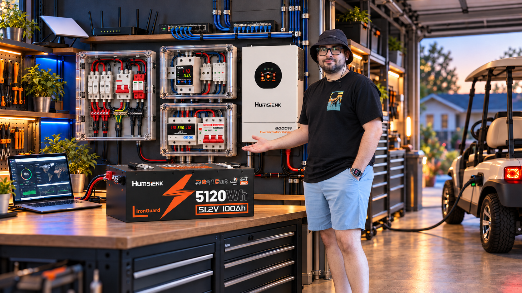
From golf cart battery to 120 V backup system
This mini series began with one practical question: can a LiFePO4 battery designed for a golf cart serve as the storage source for a residential-style hybrid inverter? The battery provides 51.2 V nominal, 100 Ah, 5.12 kWh of energy, an internal 200 A BMS, an external monitor, and a compact enclosure.
Those specifications look remarkably similar to many 48 V and 51.2 V wall-mounted storage batteries. The enclosure and intended application are different, but voltage and capacity suggested that a controlled compatibility test was worth pursuing.
Instead of connecting it immediately, I treated the experiment as a complete system build. I assembled protection and transfer equipment, studied the external BMS port, configured the inverter manually, and tested the result under a measured real-world load.
Understanding the 51.2 V, 100 Ah battery
Nominal energy is calculated by multiplying voltage by capacity: 51.2 V × 100 Ah gives approximately 5.12 kWh. That number describes how much energy can be stored, but it does not describe every limit of the system.
The BMS, cells, terminals, cabling, disconnects, and protection devices determine how much current can be delivered safely at a given moment. The external display exposes useful operating information, while a pressure-relief vent gives the sealed enclosure a controlled way to equalize pressure under abnormal conditions.
Building protection before connecting power
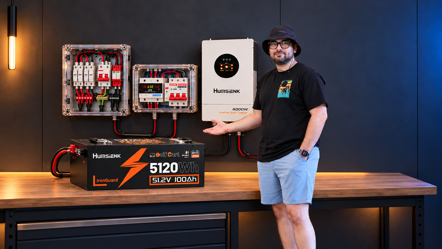
The protection box was organized around four clear functions: Grid Input, Backup Input, Transfer, and Home Output. Separating these areas makes the current path easier to understand and gives every breaker, monitor, and transfer component an obvious purpose.
- Grid Input protects the primary utility source.
- Backup Input protects the alternative inverter or battery source.
- Transfer selects between available sources through an ATS, interlock, or another appropriate method.
- Home Output protects and distributes power to the selected loads.
120/240 V is not automatically split phase
One of the most important lessons was the difference between equipment advertised for 120/240 V and equipment designed specifically for North American 120/240 V split phase. A voltage range alone does not prove architectural compatibility.
A typical single-phase device may expect Line, Neutral, and Protective Earth. A split-phase system uses L1, L2, Neutral, and Protective Earth, with L1 and L2 separated by 180 electrical degrees. Protection and transfer equipment must be selected according to the conductors it actually monitors, protects, and switches.
The same principle applies when choosing two-pole and three-pole devices. The printed voltage is only the beginning of the specification review.
Voltage protection, transfer, and measurement
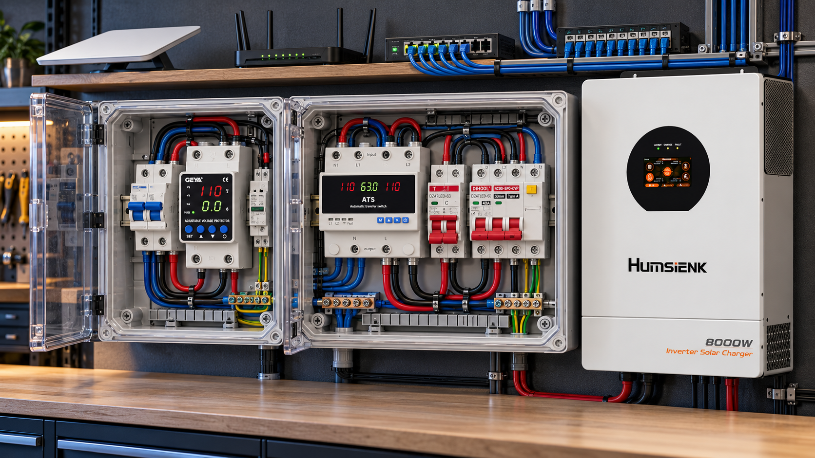
A configurable GEYA DIN-rail protector monitored voltage and allowed limits for overvoltage, undervoltage, disconnect delay, and recovery delay. This protects equipment from operating outside a chosen range, not only from a complete outage.
A GEYA automatic transfer switch then managed Grid as the primary source and Backup as the alternate source. When Grid disappeared or moved outside the configured limits, the ATS opened the source, observed its safety delay, and transferred the load. When utility power returned within range, the sequence could reverse.
A QWORK meter displayed voltage, current, power, frequency, and accumulated energy. Its current transformer also demonstrated why L1 and L2 should not be passed together through one sensor in a split-phase system. Their opposing magnetic contributions can cancel, producing a misleading or nearly zero reading.
Distribution blocks make the system maintainable
DIN-rail distribution blocks replaced improvised multi-conductor splices. One correctly sized feeder can enter a block and branch into independently secured conductors, creating a cleaner and more serviceable layout.
That matters even more in equipment exposed to vibration. Properly specified and torqued mechanical terminations reduce the chance of a loose connection developing resistance and heat, while keeping future inspection and troubleshooting straightforward.
Investigating BMS communication
The battery includes an external connector used by its monitor, so I investigated whether it could communicate directly with the inverter's BMS port. Measurements showed one pin near +13 V, Ground, and two signal lines around 3 V.
Oscilloscope measurements and connection tests did not produce usable CAN or RS485 communication with the Humsienk. The available evidence instead suggested that the display connection behaves more like a UART-style serial interface while also supplying power to the monitor.
An internal BMS does not guarantee that an external connector exposes CAN or RS485, nor that its protocol is compatible with a particular inverter. Electrical compatibility and communication compatibility are separate questions.
Operating safely without closed-loop BMS communication
Direct BMS communication is valuable because the battery and inverter can exchange limits automatically, but it is not the only possible operating mode. The Humsienk also supports manually configured battery parameters.
I configured chemistry, nominal voltage, charging limits, discharge limits, float strategy, and appropriate current limits from the battery's documented specifications. The battery's internal BMS continued protecting its cells, but manual settings remained the primary operating boundaries rather than relying on the BMS to interrupt routine misuse.
Connecting the battery to the Humsienk 8 kW
With the operating limits defined, the 51.2 V, 100 Ah battery was connected to the Humsienk 8 kW inverter. The demonstration used temporary 10 AWG conductors and was intentionally limited to approximately 15 A on the relevant test circuit.
The 1,700 W backup test
The first load was a lamp. The second was a hair dryer drawing approximately 1,700 W. With both operating, I disconnected the Grid input and allowed the Humsienk's internal transfer system to move the load onto the battery.
The lamp showed no perceptible flicker, the hair dryer continued operating, and consumption remained stable during the controlled test. The result demonstrated that this 5.12 kWh golf cart battery could power the Humsienk as a backup source without direct BMS communication when the inverter was configured manually and kept within established limits.
Equal energy does not mean identical batteries
At the level of nominal energy, 51.2 V × 100 Ah equals the same 5.12 kWh found in many residential storage products. That does not make every battery with that rating interchangeable.
This experiment shows that this specific unit can operate electrically with this inverter under a controlled configuration. It does not establish that any golf cart battery can be connected to any hybrid inverter.
- Cell chemistry and configuration
- Continuous and peak BMS current
- Charging and discharge limits
- Temperature range and thermal behavior
- Terminal design and mechanical construction
- Communication protocol and certifications
- The manufacturer's intended application
What this experiment taught me
A project that began with one compact battery became a study of protection, distribution, measurement, transfer, BMS behavior, communication, inverter configuration, and real loads.
The central lesson is simple: electrical compatibility and communication compatibility are different. The battery and inverter shared a workable electrical range even though their external communication interfaces did not speak the same language.
By measuring first, respecting the equipment limits, and configuring the inverter deliberately, the chain worked: golf cart battery to Humsienk 8 kW inverter to stable AC loads. The next question is how far the experiments can go with the Humsienk 12 kW platform.